At Sabre Plastics Tooling, we provide high‑quality spin welding services for joining thermoplastic components with speed, accuracy, and repeatability. Using advanced rotary friction welding technology, we achieve strong, clean, and consistent welds without adhesives or fasteners — ideal for circular parts and assemblies requiring airtight or watertight seals.
Our spin welding capability complements our ultrasonic and injection moulding services, enabling everything managed under one roof.
What Is Spin Welding?
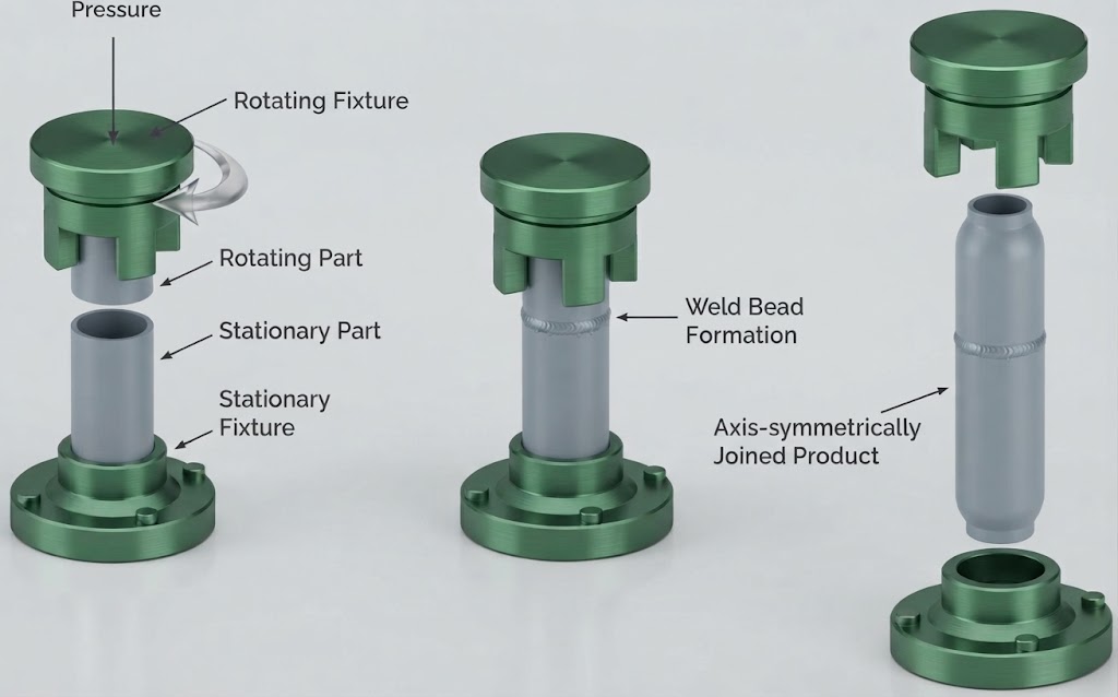
Spin welding is a friction‑based thermal joining process used to bond two thermoplastic parts. One component is rotated at high speed against a stationary part under controlled pressure. The frictional heat generated at the interface melts the material, forming a permanent molecular bond once cooled.
This method is ideal for cylindrical or symmetrical components, offering a fast, clean, and repeatable alternative to ultrasonic or hot‑plate welding.
Advantages of Spin Welding
- Strong, hermetic seals for fluid‑tight assemblies
- Fast cycle times suitable for high‑volume production
- No consumables – no adhesives, screws, or solvents
- Clean process – minimal flash and particulate generation
- Excellent repeatability and dimensional control
- Compatible with a wide range of thermoplastics
Materials Suitable for Spin Welding
Our process supports most common engineering thermoplastics, including:
- ABS – strong, rigid, and impact‑resistant
- Polypropylene (PP) – excellent chemical resistance
- Polyethylene (PE) – ideal for fluid containers and caps
- Nylon (PA) – durable and wear‑resistant
- Polycarbonate (PC) – high strength and clarity
- Acrylic (PMMA) – optical clarity for transparent assemblies
- Acetal (POM) – low friction, high dimensional stability
Applications
Spin welding is widely used across industries for joining circular or rotationally symmetrical parts, including:
- Fluid reservoirs and caps
- Filter housings and cartridges
- Automotive components
- Valves and fittings
- Consumer product enclosures
- Medical and laboratory containers
- Electrical housings and sensor assemblies
Quality & Inspection
Every welded assembly undergoes visual and dimensional inspection, with optional leak or pressure testing available for critical applications. We maintain strict process control to ensure consistent weld strength and appearance across production batches.
Spin Weld Joint Designs
Weld Joint Designs
A well‑engineered spin‑weld joint relies on controlled interference, effective flash management, precise alignment features, and robust drive surfaces to transmit torque between components. By combining these elements correctly, a wide range of joint geometries can be used to achieve strong, repeatable spin‑welded assemblies.
Below are examples of common joint styles and the design principles that support reliable weld performance.
Design Guidelines
- Incorporate locating features to ensure accurate part‑to‑part alignment during welding.
- Ensure sufficient wall thickness to resist axial weld forces
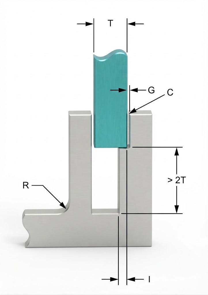
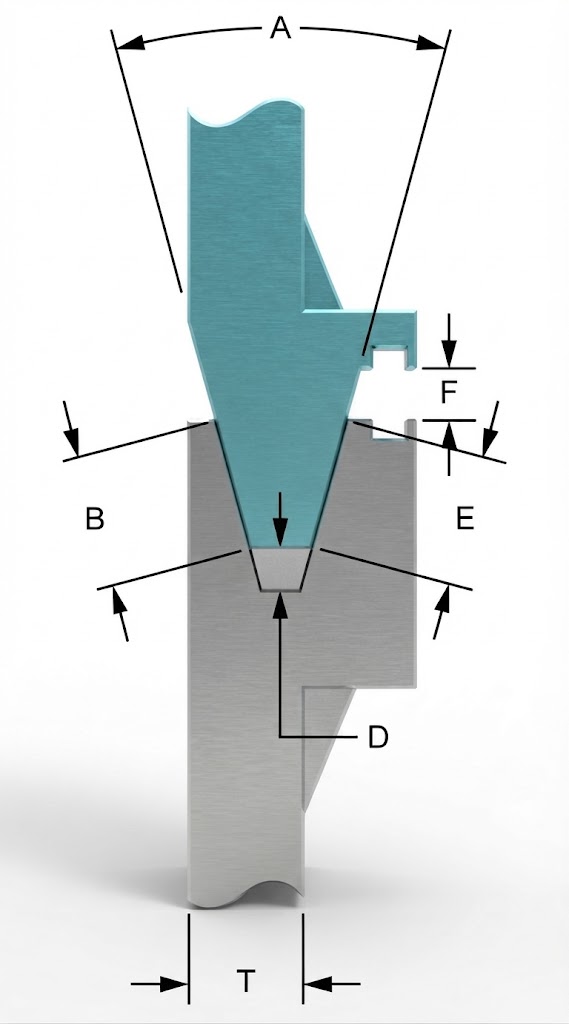
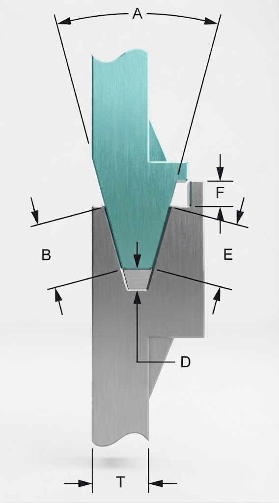
| Symbol / Parameter | Definition / Value |
| T | Wall Thickness |
| G | Gap |
| C | Clearance |
| D | Weld Depth |
| R | 1 mm (0.04″) |
| I | 0.25 to 0.50 mm (0.01″ to 0.02″) Interference |
| A | > 20 degrees |
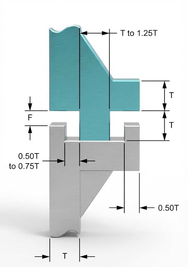
| F | > D + 0.25 mm (0.01″) |
| B + E | > 2 × T |
Flanged Shear
Butt Weld
Tongue & Groove with Flash Trap
Tongue & Groove with External Skirt
Flash Trap and Return Flange Designs
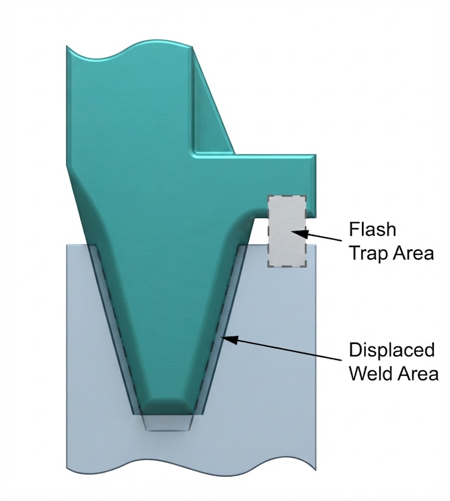
Flash Trap
The flash trap should be engineered so that its cross‑sectional area is larger than the volume displaced by the weld rib, ensuring all molten material is captured cleanly within the trap and preventing external flash.
Return Flange
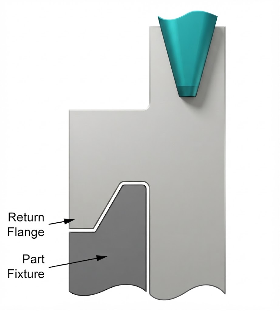
For thin‑walled components, incorporating a return flange into the joint design provides additional rigidity and helps the part withstand the axial forces generated during the spin‑welding process.